Default Interface (Simulation Environment, Learning Environment, & EV3 Programming Environment) Upon startup of the software, the default interface (pictured) is the first screen users will see. It includes the simulation environment in the top left, the Learning Environment in the top right, and the EV3 Programming environment on the bottom.  Half & Half (Simulation Environment & EV3 Programming Environment) The default user interface can be manipulated to hide the Learning Environment by clicking the
 button. In this view, the simulation environment is featured on the top, while the EV3 Programming environment can be seen on the bottom.
  Fully Expanded (Simulation Environment) To fully expand the simulation environment window, click the VRT button, or the maximize icon in the top right corner of its window. Doing this will hide the EV3 Programming environment.
  To revert back to the default display, simply click the
  button.
Simple mode toolbar  1. File management and simulator control: Simulation Projects Window / First Steps Start the simulation Stop the simulation 2. Virtual Tools: Manage robot attachments See the scoreboard EV3 Virtual Brick 3. Maximizing Windows Maximizes the EV3 programming environment Maximizes the learning environment Maximizes the Virtual Robotics Toolkit simulation window 4. Other opinions Opens the three-window interface (simulation window, learning environment, and EV3 programming environment) Opens the two-window interface (simulation window and EV3 programming environment) Close the program Advanced mode toolbar
  1. File management: Start a new project Open a recent project Save your project 2. Undo/Redo Stack: Allows you to undo or redo an action 3. Simulator control: Start the simulation. Advance the simulation in one step Stops the simulation. 4. Previous/next status check: Return to the previous state Advance to the last saved state Note: When you start a simulation and then click Pause, the software remembers where your robot was located when you clicked Pause. Each time you click Pause after moving your robot, a new state is created. 5. Manipulation tools: Truck Camera - allows you to adjust the position of the main camera at a fixed distance Move Object - the primary tool used to select objects in the model field, allowing the user to change the position of the model along the x, y, z axes Rotate Object - used to change the rotation of a selected object along the x, y, z axes Find Object - can be used to locate an object that was selected in the Objects window. See the page "Finding Objects" to learn more. 6. Robot Tools: Import Wizard - allows the user to import an LDraw (.ldr) formatted robot into the model space. Learn how to import robots here. Manage Attachments - allows the user to add or remove selected robot attachments. If no robot is selected, this button is disabled. Real-Time Data - allows the user to see the current readings from the robots' attached motors and sensors. Learn more about it here. Scoreboard - opens the scoreboard 7. Objects: Object List - lists the objects in the model field Object Library - a collection of 3D models that can be added to the model space Object Properties - set the physical properties of a selected object. Measurement Utility/Markers - allow the user to measure the distance and angle between two points on the mat. Click here to read more. Opens the EV3 Virtual Brick display Maximizes the EV3 Programming Environment The mission manager: in WRO mats, allows the user to randomize objects; on FLL mats, it allows the user to remove unwanted mission models that are loaded by default. Click here to get more information. Note: Not all levels are compatible with Mission Manager. Only the WRO 2017, WRO 2018, FLL 2017 and FLL 2018 mats allow the use of this tool.
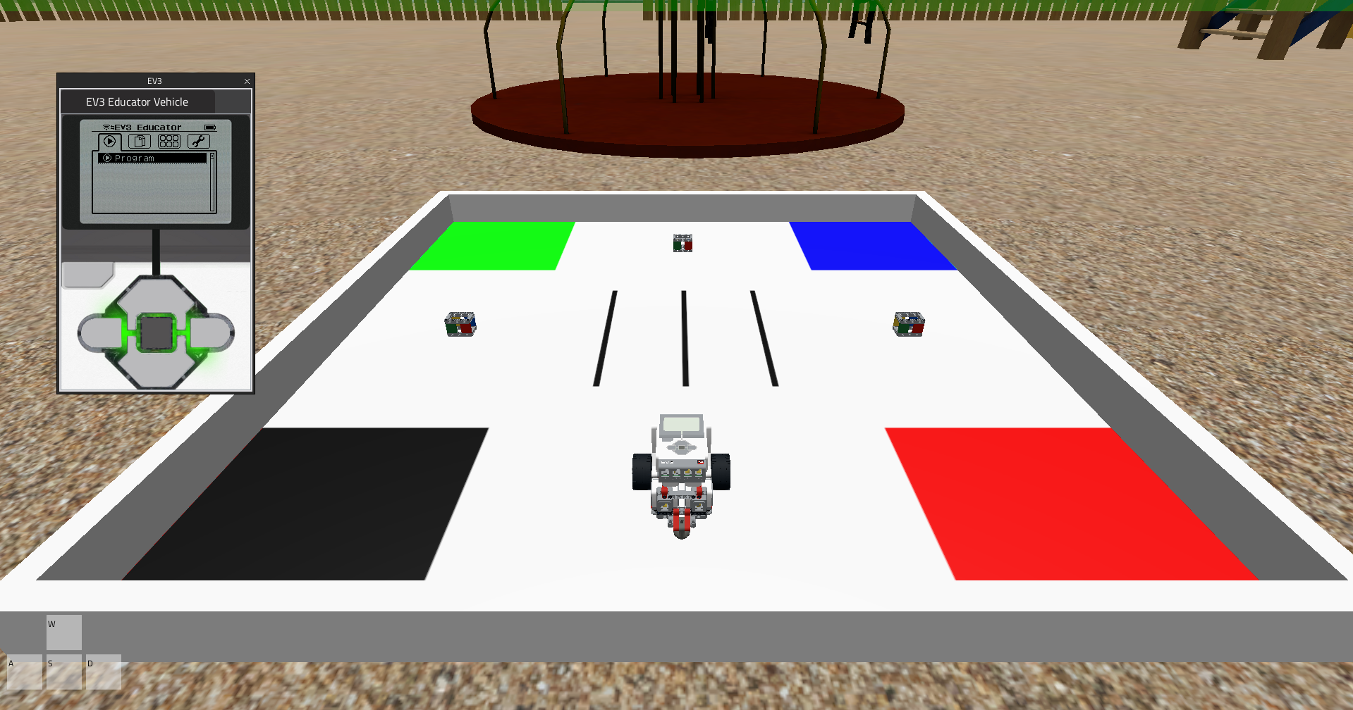
We can only drive and program our robot when the simulator is running. To turn the simulator "on", press the Play button and begin driving the robot using the W, A, S, D keyboard keys.  A green band will appear at the top of the screen to let you know that the simulator is "on". As each key is pressed, it will become highlighted in the on-screen display, and the robot will move in the specified direction. W = moves the robot forwards S = moves the robot backwards A = turns the robot left D = turns the robot right
Adjusting the Camera with the Mouse When manipulating objects in model space, half the battle is just finding a good view to work with. Using the mouse, there are several ways to adjust the view: 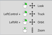 Look by right-clicking on your mouse to look around. Truck by holding the Control key + right-clicking. Orbit by holding the Alt key + right-clicking. Zoom by using the middle mouse scroll wheel. Alternatively, we can also use the keyboard to zoom in and out from an object by pressing the ’+’ and ’-’ keys. Camera tracking options
 Near / far clip options, refer to the near and far plane of the viewing field, the region of space in the modeled world that is visible on screen. Anything closer to the eye than the near clipping distance isn’t displayed (it’s too close), and anything further away from the eye than the far clipping distance isn’t displayed either (it’s too far away).
  Camera presets allow us to reorient the camera along a number of predefined perspectives, such as from the top of the object, the left of the object, the front of the object, etc.
  Perspective / Orthographic view toggle, an orthographic view is typically used in engineering applications for viewing objects at a fixed depth. That is, as the camera zooms in and out, the objects in view will not become either bigger or smaller. This is in marked contrast to a perspective view, which is typically how we normally see the world, in which as we get closer to something it becomes bigger, and as we get further away from an object it appears smaller.
  Camera tracking options, allow us to select an object in model space and to have the camera follow it as it moves. Powered by Froala Editor


 . 2. Select the object you wish to locate from the list. 3. Click on the Find Object toolbar button
 .
.  Find Object